
Convert Surfaces into Printable Solid 3D Models with Metashape & MeshMixer
In this short article, we’re going to share Mr. Andrew Sink’s brief but helpful instructions on how to use Metashape and MeshMixer to convert a series of surfaces into a printable solid 3D model.

Anytime that we scan something and we don’t have a full 360 view of an object but only wind up with partial surfaces like above picture showed. And Mr. Andrew Sink is going to print a Halloween shield with Anet ET5X 3D printer which is converted from scanned images. Step by step, we’ll learn how to do it.

Agisoft Metashape is a pretty powerful but a little complex software that performs photogrammetric processing and generates 3D spatial data. We can use it to mesh 3D scanned data into a complete 3D image.
Step 1
Upload initial array of pictures inot Metashape and stitch them together and create a sparse point cloud.

Step 2
Use tie point function to bundle all these pictures into one cohesive scan. And we have a dense cloud that contains a lot of colored vertices.
Step 3
By creating triangulated mesh we can make the cohesive scan image into editable STL file.

Step 4
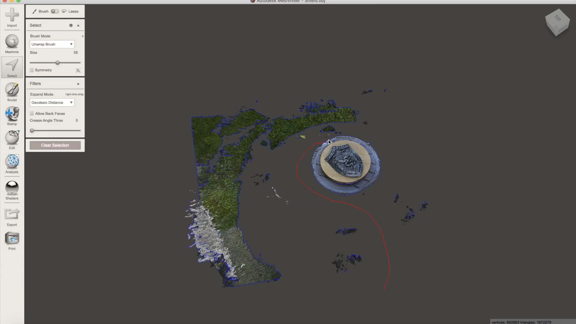
Import the whole piece into Mesh Mixer.
Step 5
As we can in previous image, there is unnecessary background like a door in the file. We can modify it and trim them off and the quickest way to do it is to select big chunks first.
Step 6
Trim unnecessary edges off from the shield. This step surely consumes time. Be careful with all trimming if you want to get a good shield. Take your time and slowdown in every trimming. One of the things we can do here is to use the slash tool and the smooth boundary option which will give us a nice clean line instead of following the triangles. It’ll optimize for a relatively straight line. That’s a very quick way to get to a better looking surface than having a bunch of triangular edges.


Step 7

To complete the transition from surface to solid model, use the extrude command and set negative extrusion value to bring down a bottom for the shield.
Step 8

Use plane cut function to trim the bottom to a flat surface at the position you want.
Step 9
Bring in a cylinder and orient the cylinder until it looks like a good approximation of that profile.


Step 10
Now we can pull the two together and subtract out any difference. This leaves us with a curved bottom profile for the shield. It’s much cooler than a flat bottom.

Step 11

Step 11
Orient the model upright in a slicer software and this will help a 3D printer to print it out with as much details as possible.

Step 12

Slip the shield right in the middle and rotate the lower part upright.

This allows both parts printed out with nice flat bases and capturing as much details as possible.
Step 13
Enlarge the model and print these two parts simultaneously on an Anet ET5X 3D printer.

The Anet ET5X 3D printer is a large volume printer with a print size of 300*300*400mm. This allows Mr. Andrew Sink to enlarge the model for a better comparison with the original shield and simultaneously printing also saves time.

Print Setting

If you have any questions, please feel free to leave comments down below, our guys are waiting to help you. Joining our community is also a good idea, you can get information, model files, g-code files, tutorials and find the enthusiasts as you are. It's a place where creative people gathered, just hit the link: https://forum.anet3d.com/
Leave a comment